


CIRCUIT BREAKERS
Circuit breakers are simply switches that have an internal mechanism that senses an overcurrent in the circuit. This could be caused by overloading the circuit with too many appliances connected and operating at the same time. It could be caused by one piece of equipment or appliance that uses a higher current beyond what the circuit was designed to handle. It could also be caused by a short-circuit. The circuit breaker is designed to trip (open) under these conditions. Circuit breakers are designed to protect persons and property from a possible fire. If the circuit breaker itself is defective and does not open or trip when there is an overcurrent, it could cause a fire. Standards have been set up for satisfactory circuit breaker manufacturing.
When checking circuit breakers you need to check visually and manually the exact position of the switch handles. A breaker is ON when the switch handle is fully in the ON position. A breaker may sometimes look ON but it is OFF. A breaker that looks ON and is somewhat in the midway position is OFF and it needs to be reset. Some breakers after they trip, may need to be reset by switching it in the OFF position first, then switching it to ON. You may touch the handles of the circuit breaker switches and you will not be shocked. The handles of a circuit breaker are insulated; thus carry no electrical current.
PLUG FUSES
Older homes used fuses for overcurrent protection. Today, many older homes are upgraded to circuit breakers. In homes with fuses, screw type plug fuses were used. They were made with glass or the top being transparent. This makes it easy to see if the circuit opened by a burnt and melted fuse link. Fuses should always be replaced with the proper sized current protection; replace a 15 amp fuse with a 15 amp fuse; a 20 amp with a 20 amp; and so on. The problem with ordinary plug fuses is that you can increase the amp size on a circuit that may not be designed for the increased amp load. This could pose a fire hazard. One solution to this problem is to use Type S fuses. Type S fuses are rejection or tampering resistant; that is, they have a rejection design which offers resistance with tampering with the established branch circuit design by rejecting certain higher amp rated fuses from being inserted in the holder. You insert a properly rated adapter into the fuse baseholder. The appropriate size fuse screws into the adapter. These adapters limit the ampere rated sizes of fuses and will not allow an oversized fuse to be used. Caution: once the adapter is installed it cannot be removed.
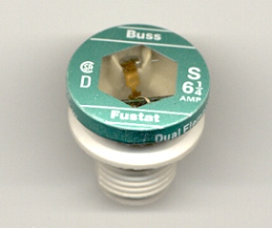
Type S Fuse

Type S Fuse Adapter
If you want to simply disconnect a circuit, remove the fuse from the baseholder by unscrewing it in a counterclockwise direction.
If it is not noticeable through the transparent material that a fuse link has blown or melted open, you may check the fuse by using a voltage tester. Check that the fuse is firmly inserted by twisting it in a clockwise direction. Next, hold one test lead on the neutral bus bar or adequate ground and with the other test lead touch the screwshell of the fuse or if visible, the corresponding circuit wire terminal (usually, horizontally left or right of the fuse).
CARTRIDGE FUSES
In residences with pool motors, air conditioning or other equipment, cartridge fuses may be used in disconnects or fuse boxes to protect motors, compressors and associated equipment from overcurrent conditions.

Another Type of Cartridge Fuse
THE FOLLOWING INFORMATION IS FOR THE PURPOSE OF HELPING A COMPETENT PERSON WORK SAFELY WITH ELECTRICITY. THE TECHNIQUES AND METHODS SHOWN HERE ARE NOT ALL THAT A PERSON MAY NEED TO WORK SAFELY AND THE ARTICLE DOES NOT INTEND TO IMPLY THAT THIS IS COMPLETE FOR ALL WORKING SITUATIONS. IF YOU WORK WITH ELECTRICITY AND ITS ASSOCIATED EQUIPMENT AND USE THESE TECHNIQUES AND METHODS, YOU DO SO AT YOUR OWN RISK.
THINGS TO REMEMBER TO WORK SAFELY WITH ELECTRICITY
1. ALWAYS ASSUME THAT EQUIPMENT OR DEVICES ARE HOT (electric power is ON and is present at the device or equipment).
2. ALWAYS DISCONNECT, that is, turn off electricity to the devices and equipment that you are going to work on. You can disconnect the electricity by:
3. Ensure that the electricity WILL NOT be turned on by self or other persons. This can be done in one or more ways.
THE FOLLOWING SHOULD ONLY BE DONE BY SOMEONE MENTALLY AND PHYSICALLY (DEXTERIOUSLY) COMPETENT.
In cases where you cannot trust anyone, you may need to physically open or remove the circuit breaker panel cover and disconnect the hot wire from the breaker terminal. First, switch off the circuit breaker of the circuit you are working on, before disconnecting the wire. A flat head or phillips screwdriver can be used to disconnect the wire. For additional safety measures, you may want to stand on a rubber mat or dry wood for insulation; especially if the ground is damp.
MAKE SURE THAT YOU AND YOUR SCREWDRIVER DO NOT COME IN CONTACT WITH ANY BUS BARS OR OTHER SCREW TERMINALS EXCEPT THE ONE THAT IS CONNECTED TO THE WIRE YOU ARE DISCONNECTING.
Bus bars are what the circuit breakers or fuse baseholders are connected to. Bus bars are HOT and you can receive an electric shock and serious burns if you touch one while you are grounded. You may touch the insulated part of the wire; it does not conduct electric current. You do not have to unscrew the circuit breaker terminal completely to remove the wire. When removed from the breaker terminal, tape the metal part of the disconnected wire with electrical tape; it is not to come in contact with any bus bars or terminals. Carefully move the wire out of the way in the box and reinstall the panel cover. When reinstalling the wire, apply firm pressure to the terminal screw on the circuit breaker, but do not strip it.
4. Test the device or equipment to make sure the electricity is OFF. This applies only to the circuit or circuits which you have disconnected power from. Other devices in the building location may still be hot.
5. When you return to your work after a break, such as lunch, REPEAT STEPS 1 – 4.
By following these rules to the letter, you should never receive an electric shock by the electric utility service; provided you are working on the side in which the electricity has been disconnected (turned OFF) and that no one overrides the safety measures implemented.
A question was asked: “The letters, like a FRN-R or FLM or FNM before the Ampere rating (amp), are they referred to specified conditions or is only manufacturers codes?”
Answer: Each manufacturer has their own blend of alphanumeric characters to signify a particular fuse. I am not sure if each character of a particular part number of a fuse serves as a code to explain particulars of that fuse. However, some characters do represent something special or different.
For example: Bussmann has a named fuse FRN. The amperage rating will follow these characters. Like this; FRN-1. One (1) is the amperage rating. I do not know if and what FRN stands for. These fuses are called Fusetron. Is it short for that? If so, then what would the competitor’s equivalent part number represent. Mersen (Gould/Ferraz Shawmut) has an equivalent part series TR. These are called Tri-onic. Again, the amperage rating follows the alpha characters; like TR2.
Now look at this. Bussmann has a fuse named FRN-R. The R after the hyphen is a symbol to represent that the particular fuse is a “rejection” type fuse. Their design is slightly different and have higher interrupt ratings than the FRN type fuses. You cannot physically use an FRN fuse in an FRN-R type fuse block. These fuse blocks are designed to accept only FRN-R type fuses. However, you can use an FRN-R type fuse in an FRN type fuse block. Mersen (Gould-Ferraz Shawmut) uses the symbol TR(amp)R; like this TR2R. The R after the amperage rating signifies “rejection” type fuse. Littelfuse names their equivalent fuse FLNR. Edison has ECNR. With these, I do not know the significance of the first three characters, but the R probably represents “rejection” type.
It appears that the manufacturers try to assign characters of a particular fuse that will distinguish themselves from their competitors, but at the same time have some kind of reference to the type fuse. But what does KTK represent? This is a Bussmann fuse called Limitron. How does two Ks fit into this? It is also fast-acting so a T, which on some fuses might represent time-delay, could not be applied here. Was this an arbitrary decision to name these fuses as such? The manufacturer should know. Littelfuse’s equivalent part symbol is KLK. Maybe the L represents Littelfuse.
So it appears that the alpha characters can represent specified conditions, such as “rejection” type and/or also signify a code for manufacturers’ parts. Whether these characters always have a logical signification, I am not convinced.
Electricity can be very dangerous when handled improperly. Not only can a person die from an electrical shock, but also he can receive serious burns. Loss of property can be attributed to fire because of improper wiring or failure of electrical devices and equipment. Some simple electrical devices and equipment are: circuit breakers, fuses, switches, receptacles, lamp fixtures, small and large appliances, heating, wiring, and associated equipment.
Working with electricity can be safe. The key is to never work on an energized circuit. This, of course, is easier said than done for the fact that electricity cannot be seen, heard, smelled, or tasted. Sometimes, when only the conductor of current is touched, do we know electricity is present. This does not have to be this way.
The following electrical safety tips are written so that the person working on electrical equipment will become more aware of what they are doing so they may do it safely.
Ampere rating is an electrical current value given to every fuse. This value is the allowable current which can flow continuously through the fuse under specified conditions. This value can also be referred to as current-carrying capacity or ampacity. Refer to the NEC (National Electrical Code) requirements when selecting a particular fuse for a circuit.
The following is some examples of part numbers and where the current rating (amp) is listed.
FRN-R-(amp); FRS-R-(amp); TR(amp)R; TRS(amp)R; FLNR-(amp); FLSR-(amp); LPN-RK-(amp) LLNRK-(amp); KTK-R-(amp); FNQ-R-(amp); ATQR(amp); ATMR(amp); LP-CC-(amp) A2D(amp)R; A6D(amp)R; LPJ-(amp)SP; AJT(amp); JKS-(amp); FNM-(amp); FLM-(amp); MDL (amp); AGC (amp); 313(amp); 233(amp); FWH-(amp); A50P(amp); A25X(amp).
“Interrupt rating” is not the same as “ampere rating,” even though both these are dealing with current values.
When reading technical data about a particular fuse you will see symbols or rather abbreviations such as I.R. or IR which refer to “interrupt rating.” Other abbreviations could be A I.R., A IR, or kA I.R. which is “amperes interrupt rating” or “kilo amperes interrupt rating” respectively.
Given a particular rated voltage, this current rating refers to the maximum amount of instantaneous current that can be interrupted safely without explosion or damage to the fuse link carrier, such as the cartridge or tube. This interruption of current flow can occur in fault or short circuit conditions. This current rating has been approved through standardized tests.
Interrupt rating is also referred to as “breaking capacity.”
When a short circuit occurs, a current limiting fuse, within its current limiting range, opens within ½ cycle. This prevents the damaging overcurrent to reach its maximum instantaneous short-circuit value in the circuit if that fuse were replaced with a solid conductor of comparable oppositional characteristics to current flow. The instantaneous peak let-though current is the actual maximum let-through current value in the circuit before the fuse opens and clears the circuit under short circuit conditions.

Example Current Limitation Sine Wave
TIP: How to repair a backhoe damaged underground section of rigid conduit without union fittings.
First remove all conductors.
Use reciprocating saw to remove damaged section of pipe. Clean the burrs off ends of existing conduits to be mated by reaming with a half-moon or round file depending on size of pipe. Clean off any rust or debris the entire length of at least an inch and a half or two inches from the end of the conduits.
If conduit section removed was bent as damage, the remaining ends cut to be mated should now be able to accommodate a new straight section of pipe or at the least a light bend or kick in the new section if needed.
Cut your section of pipe to install to size after you have made any necessary bends. Make the space tolerance between the existing pipe ends and new pipe ends as small as possible. This will insure the best fit for a properly positioned coupling. If the length of rigid pipe to install is less than 10 feet you will need two appropriate sized threadless compression couplings for rigid conduit.
Midway inside the threadless compression coupling is a “pipe stop” or ridge. You need to remove these on both couplings. This will allow the full length of the coupling to move freely on the conduit. A half-moon or round file works good to remove these stops. Remove the compression rings and nuts before you do any filing.
Slide both couplings on the pipe to be installed. Install new section of pipe by sliding the coupling into place on existing conduit end. Make sure that you center the couplings between the ends of pipe so that the compression rings on both ends of coupling will clinch the pipes completely. If you do not center the coupling properly you could have a compression ring clinching partially the conduit end and partially the dead space between the conduits. This would be a bad installation.
Tighten up all connections. As an added benefit to installation, install black vinyl 10 Mil tape over the coupling and the length of the pipe.
Install new conductors.